The GUI
First of all, the GUI is written in Java, so you need a JVM
(client JRE is sufficient) installed.
With an installed JRE, double-clicking the JAR will start it.
Alternatively, you can start the JAR via
java -jar NGenUSB.jar
or on Windows (if you don't want a console)
javaw -jar NGenUSB.jar
To get access to the device via USB HID, the Java
HID API is used which is supported on Windows, Mac OS and Linux.
Therefore the application will also work only on these supported systems.
If you need a fancy desktop icon, there are icons provided in PNG and ICO
format in several sizes.
The main window
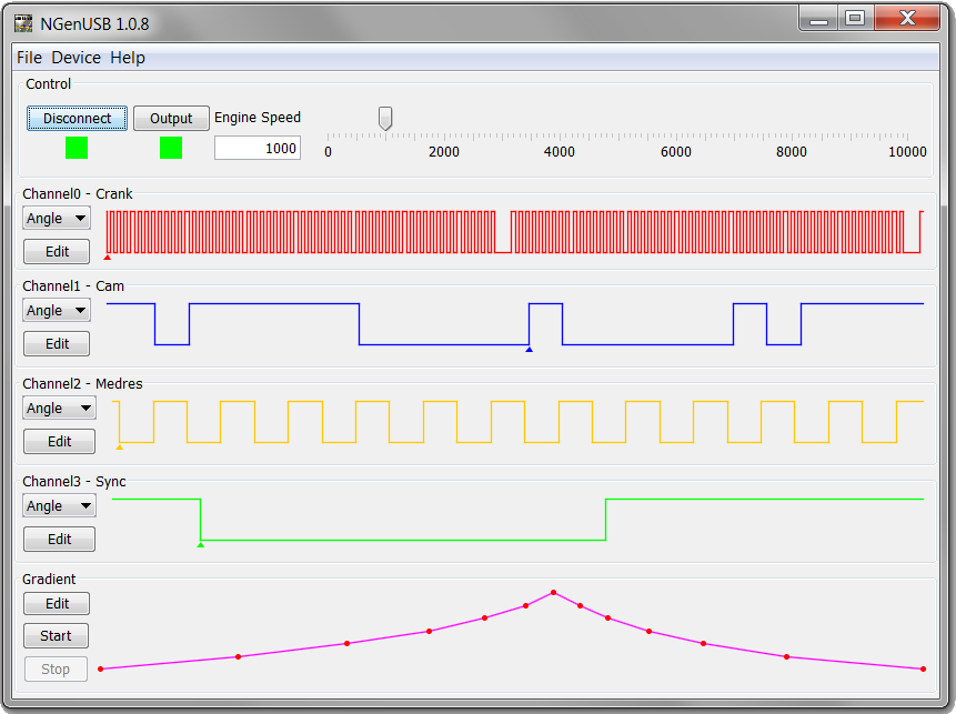
The main window will give you access to the most common functions and
will show you all the important information.
Control Panel
With the Connect/Disconnect
button, you can connect/disconnect the device.
Red means "not connected", green means "connected"
As soon as you're connected, the current setup, signal shapes and gradient
will be downloaded from the device and displayed
With the Output button, you can
switch off all output or re-enable them again.
Red means "outputs off", green means "outputs active"
Note that switching outputs off will switch the push-pull driver to high
impedance mode. So the 100k pull down resistor in each output will pull it
to ground.
To the right is a text box and a slider to set the input speed. In
gradient mode, the current engine speed will be displayed here.
Channel Panels
There's one panel for every of the four channels. To the left, you can
switch the channel mode or edit the channel data.
To the right is a preview of the current signal. When clicking into this
preview window, a cursor will be displayed that snaps automatically to the
next edge and shows its value.
There are three channel mode available: Angle, Time and PWM.
Note that due to implementation limitations, the channels 1&2 form one
group and channels 3&4 form a 2nd group.
Within such a group of two channels, you can only use either time mode or angle
mode, but not angle mode on the one channel and time mode on the other.
So if e.g. channel 2 is in angle mode and you set channel 1 to time mode,
also channel 2 will be switched to time mode. PWM mode however is always
selectable without influencing other channels.
Angle Mode
In angle mode, the period data for the channel is extended to 720° if this
is possible. If the angular length of the channel data is not an integer
divider of 720°, the preview will be inaccurate.

In edit mode, you are able to edit the shape by defining offset (°Crank) and
polarity of the first edge (marked with the little triangle below the
waveform) followed by a number of periods shown in a table.
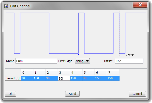
When selecting a table column, the cursor will highlight the start of the
period in the preview window.
Note that pressing enter is needed to actually change the value. A reddish
background of a table cell hints that the value is currently invalid.
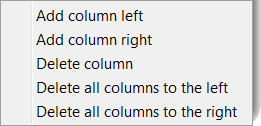
Table entries are in °Crank. You can drag'n'drop columns or add/remove
periods through a popup menu:
In edit mode, the 720° extension is displayed as area with darker grey
background
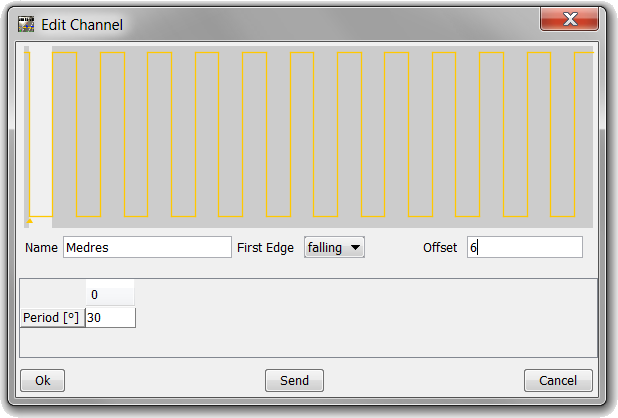
If the sum of all periods is not an integer divider of 720° (or a multiple thereof), the extended
area will have a reddish background to warn you and to show that the preview
is inaccurate
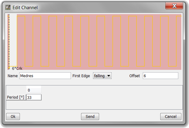
Ok will accept the changed
signal but won't upload the new data to the device.
Send will accept the signal and
upload the new data to the device.
Cancel will discard all changes and
bring you back to the main menu.
Time Mode
In time mode, no extension is performed as in angle mode. The preview will
be just a representation of the channel data.

The edit dialog for time mode is nearly identical to angle mode - the main
difference is that the value are times in microseconds.
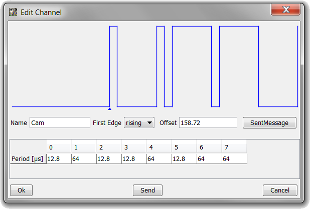
The only fancy option here is SentMessage which opens another dialog to
create a SENT
message from given parameters:
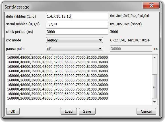
When pressing OK, the periods for the SENT message are copied to the channel
data to simulate a SENT sensor.
You can also Save the setup to an INI file or load an INI file back into the
SENT editor. Cancel will bring you back to the channel editor without
altering the channel data.
PWM Mode
In PWM mode, the channel data has no influence on the waveform. Instead you
can enter the frequency, duty cycle and polarity directly.

As with other edit fields, you need to press enter to take over a value and
invalid values will be marked with a reddish background.
Gradient Panel
To the left, you can start/stop the engine speed gradient. To the right
is a preview of the current gradient.
When clicking into this preview window, a cursor will be displayed that
snaps automatically to the next edge and shows its value.

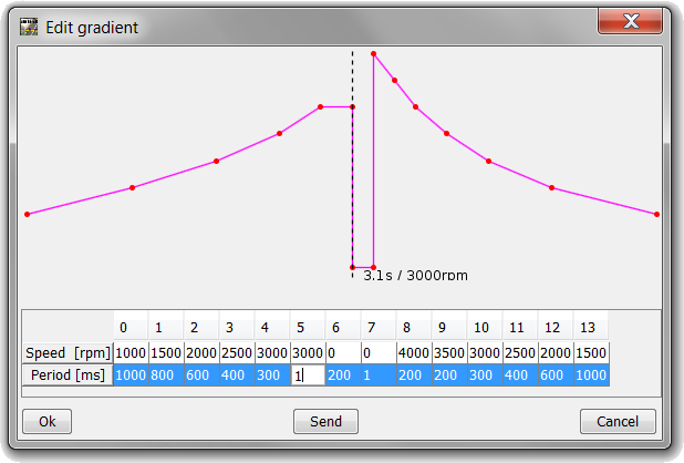
In edit mode, you can edit sample points where each point consists of an
engine speed and a distance to the next sample point (in milliseconds).
Dragging, removing and adding columns works the same way as in the channel
editors.
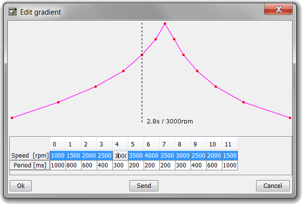
Note that between sample points, an automatic linear interpolation is
applied. If you really need an immediate change, you can force this by
adding a sample point with minimum period (1ms):
The File Menu
Nothing spectacular here. You can save the current setup to an ini file,
restore it from an ini file or exit the GUI.
The Device Menu
Create Glitches
This item allows you to create glitches on the selected output signals.
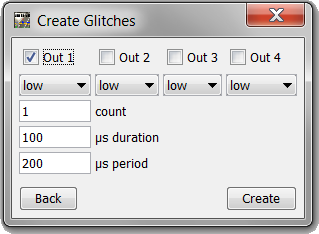
In the first line, select the channels on which to create outputs.
The list boxes below allow you to select if the level should be low or high
during the glitches.
Using count the number of glitches
to be created is defined.
With µs duration the duration of a
single glitch is determined in microseconds.
Finally µs period defines the
period for repetition of glitch creation in microseconds (must be larger
than µs duration)
Bidirectional Setup
This item used to configure the bidirectional sensor setup.
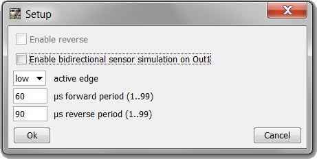
With enable reverse the simulation
of backward rotation is enabled/disabled.
Using Enable bidirectional sensor
simulation on Out1 the special bidirectional mode for channel 1
(out 1) is enabled/disabled.
In this mode, the angular position of the inactive edges is ignored and
instead they are created at a defined (rotation dependent) time period after
the active edge.
Through active edge, the edge can
be selected that will keep its angular position, while the other (inactive)
edge will be created at a defined time after this edge.
The two values µs forward/reverse period
define the active period (between active edge and inactive edge) for forward
and backward rotation.
Values are in microseconds. Note that value > 99µs are invalid as longer
periods would collide with the 100µs tooth period at 10000rpm.
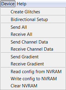
Send All / Receive All
Will send all channel/gradient/configuration data to the device or receive
all the data from the device. Usually not needed but just in case you want
to trigger the upload/download manually.
Send / Receive Channel Data
Will send all channel data to the device or receive all the data from the
device. Usually not needed but just in case you want to trigger the
upload/download manually.
Send / Receive Gradient Data
Will send the gradient data to the device or receive it from the device.
Usually not needed but just in case you want to trigger the upload/download
manually.
Read Config from NVRAM
Reads all channel/gradient/configuration data from the NVRAM and then
downloads it from the device to the GUI.
Note that at powerup, the device will also restore the configuration from
NVRAM (if there is a valid configuration stored) - else a default
configuration from the ROM is used.
Write Config to NVRAM
Stores all channel/gradient/configuration in the 32k NVRAM. Note that this
is only possible if you don't use all channels and the gradient data to
their full extent.
Clear NVRAM
Invalidates the NVRAM by overwriting the NVRAM header. This will restore the
default ROM configuration immediately and also force a download to the GUI.
Note that with invalid NVRAM header, the default ROM configuration will be
used at startup.
Back to main page


